In many material-handling applications, it is necessary to make adjustments in the load support center distances to accommodate loads of different lengths or widths, especially if these loads have to be captured to avoid shifting. These loads can come in a variety of shapes and sizes, and encompass a variety of industries. Similar designs concepts are used in tooling storage, automated inventory systems, and in large product handling systems.
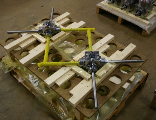
In this case, the customer’s design concept included two carriage beds supported on rollers and running on a guided track. These carriages had to either converge or spread apart to accurately position under specific support points on loads of different lengths.
In some applications of this type one carriage may stay stationary while the companion carriage may just move away or get closer. This can be accomplished with a single belt drive, screw, or cylinder. But in other material-handling applications, both carriages have to move in opposing directions from a center position, which is what was needed here. Because of the size of the adjustment length required, the customer’s preferred method was via a belt drive. In essence, he wanted to recreate a larger version of a standard belt drive actuator, which many of you are probably familiar with. There was to be a belt bracket attached to the carriage. As the belt was driven it would pull or push the carriage, along the track, depending on the direction of rotation.
So, in the case of two carriages, there will be two-belt systems. But they clearly have to move in opposite directions to expand and contract from a center point. To achieve this with a single drive means the belt has to be connected to counter-rotating output shafts.
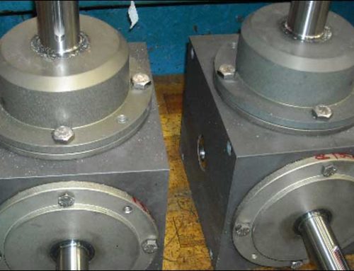
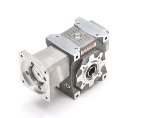
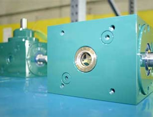
Our suggestion for this was to incorporate our Tandler Spiral Bevel Gearbox Series EA with an auxiliary shaft. This version has two pinions assembled at 180 degrees that mesh with a single drive gear. This results in two opposite output rotations with one input.
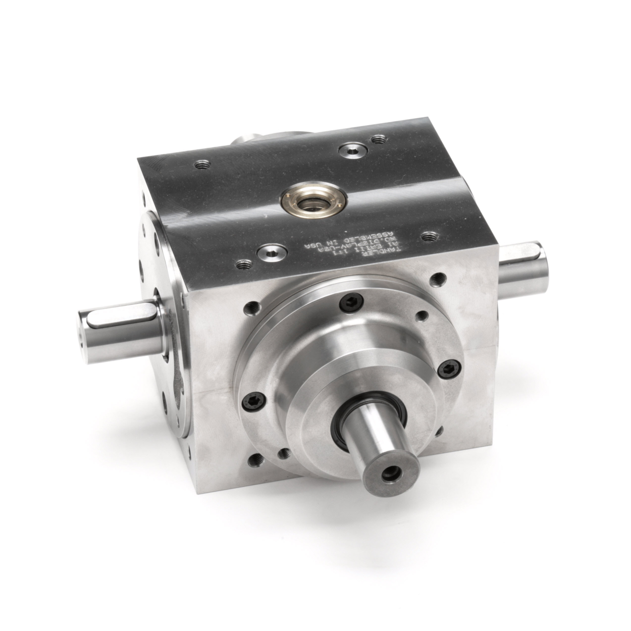
While this gave us the required motion, there was a limitation. With the internal drive gear mounted over an internal shaft, the ratio options were minimal. Although with a reduced input shaft size a maximum ratio of 2:1 could be realized, the normal shaft size allowed only a 1.5:1 ratio to be incorporated. This wasn’t really enough ratio to optimize the performance of the servomotor that would be controlling the movements.
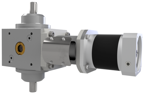
To increase the ratio, which would not only allow the motor to work with a better speed range, but also reduce the system inertia reflected back to the motor, we suggested the addition of a Planetdrive planetary gearhead that could be flange mounted to the input of the bevel box and coupled using an EK2 series elastomer jaw coupling. Using just a single-stage planetary reducer would allow an overall ratio of up to 15:1.
So, the system configuration consisting of servo motor, gearhead, backlash-free coupling, and low backlash counter-rotating spiral bevel gearbox, all mounted together as a sub-assembly, was identified. But what sizes and torque capacities still had to be determined.
Because this application was really a motion control application, with stops and starts, all the data necessary to calculate acceleration torques were required.
The initial step was to identify the weight and inertia of the carriages to be moved. The coefficient of friction between the roller wheels and track materials modified the effective weight value, which reduced the force values necessary to move the load. Taking into consideration the drive pulley diameters and the acceleration and deceleration rates needed to meet the positioning cycle, the required torque values to accelerate the load were determined. Adding service factors for the number of cycles in an hour and a safety factor to cover any mishaps resulted in an effective torque that could be used for component selection.
When an acceleration torque value has been determined it’s best to work backward to the motor. The efficiency of each transmission device should be considered and the inertia of each component is reduced by the square of the ratio of each reducer in front of it. This then results in a collection of reflected inertias, to the servo motor shaft, which can then be used to calculate the motor torque necessary to accelerate the load to a given velocity.
I know I am a little calculation light in this example, but formulas can easily be found and used for your specific applications. The point here is to identify the thought process and situation parameters. While the concept is similar to most other motion control applications, the design configuration and performance goals add to the selection challenge. And considering that most gear products are more accurately rated for continuous duty, choosing the optimal mechanical drive products for intermittent motion profiles is a bit more difficult to pin down.
However, through joint analysis with the customer to determine acceleration requirements, re-rating gearboxes for the expected duty cycle, selecting gearbox ratios to optimize efficiencies and motor performance, and selecting appropriate products to get the correct rotations in an acceptable envelope, a final design meeting all the parameters was the happy ending to the story.
DieQua works with many of our customers to come up with sub-assemblies or multi-component systems using more than one of our products. The breadth of our capabilities allows us to provide unique solutions not available from other sources. It’s through understanding our customer’s needs and applying the proper products to meet them that we are able to offer outstanding value.