There are a lot of processes that require continuous, smooth running, rotary motion. But sometimes two different speeds are necessary. Inverters or servo gearheads can’t always deal with the differences.
In a lot of applications, variable speed can be accomplished with an inverter. By varying the hertz a motor can operate at a relatively wide speed range. However, when running above 60 Hz there is usually a drop off in output torque. And when the hertz drop below 20, in many instances additional cooling is necessary because the fan isn’t turning fast enough. And when running as low as 2 – 3 HZ the signal becomes erratic and rotary motion isn’t as smooth.
With servomotors, variable speed is also possible. We’ve probably all seen the display at trade shows where the servo makes small steps then quickly returns to another position. But in very slow continuous motion the resolution on a servo is drastically reduced. And the technology is probably overkill when only two speeds are necessary and precise positioning is not required.
In both these instances, the mechanical advantage is not being optimized when the slow-speed operation is the primary task, but the high-speed operation is also required. You may think this situation is rare, but we have several situations where this is required.
In the most recent application, the customer needed an extremely slow output rotation for a machine that was used to grow crystals. The requested overall motor to output ratio was almost 3500:1 if this was the only requirement a variety of gear products could have done the job. However, it was also necessary to be able to drive the load at a ratio of 3:1. This was necessary for machine set up and some cleaning requirements.
To be able to achieve an almost 1200:1 speed variation out of a single gearbox required a unique solution. And although it was probably possible to do something electronically, the system really had to be optimized for the slow-speed activity. Therefore incorporating mechanical advantage through the use of a gearbox, and allowing the main drive motor to operate at the optimum speed for efficiency and precise control, was the preferred design goal. But how to achieve this was the question?
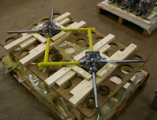
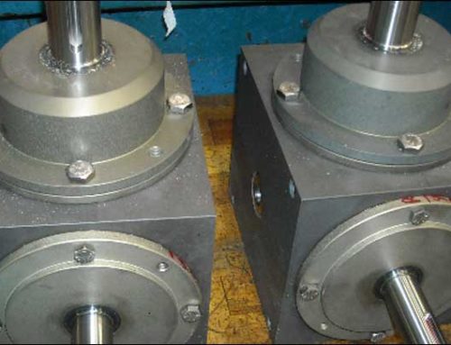
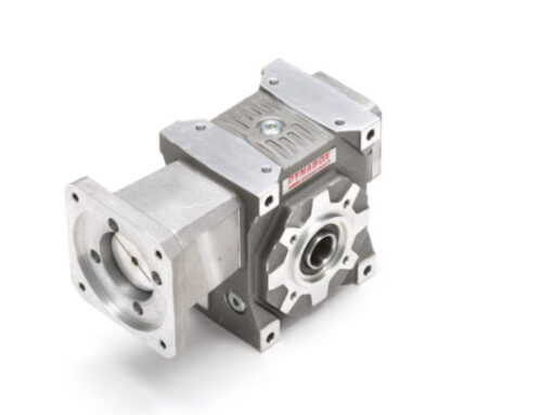
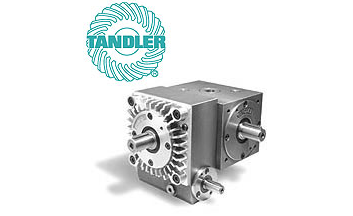
Our solution was to use one of our Variable Speed Gearboxes manufactured by Tandler.
The Speed Correction Drive gearbox is essentially a planetary reducer with dual inputs. One lower ratio input shaft drives the planet gears from the sun gear, exactly like all other planetary design reducers. The second higher ratio input shaft drives the ring gear, which is normally fixed in standard planetary reducers. Driving in this direction is similar to a worm gear reducer. But instead of driving the output directly, the ring drives the planet gears, which drive the output.
A unique characteristic of this type of gearbox is the possibility of driving both inputs simultaneously to get a narrow range variable output speed or a positional readjustment. This is often used by driving the lower ratio shaft as a standard reducer while also driving the higher ratio shaft to vary the output speed up or down a few percent. Even more common is to drive the high ratio shaft intermittently to quickly accelerate or decelerate the output shaft in very small amounts to change the relative angular position of the output shaft relative to the primary input. This is typical in registration, timing, and tension control applications.
But, back to our application for this customer, since the box is being used differently. To achieve the wide span of two basic speeds we selected a base gearbox ratio of 3:1 with a standard 1750 rpm motor speed. Other ratios between 1:1 and 4.5:1 are also available. For the slow speed requirement, the customer started with a small servo gearmotor with 25:1 ratio. The output of this gearmotor was then mounted to the high ratio shaft of the Speed Correction Gearbox, in this case with an additional 135:1 ratio, for an overall ratio of 3375:1. Other ratios are also available in addition to 135:1. Other options include 67.5, 45, and 33.75:1 allowing for quicker response times and wider range speed control.
The result was a two-speed gearbox design with an optimized low operational speed and a high-speed capability for the setup and cleaning needs that met the original parameters.
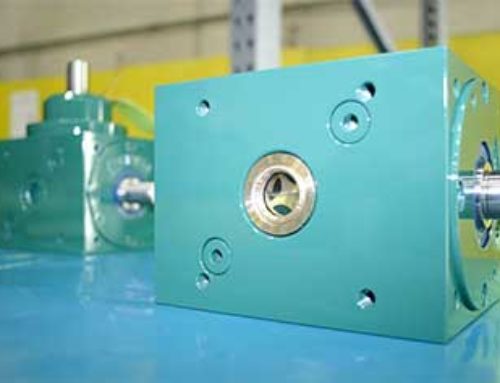
One additional component that was necessary in this case was a brake. When driving the high ratio shaft, torque flows in the path of least resistance. The low ratio shaft and connected drive motor have a lot less resistance when not energized than the intended load. With our right-angle bevel gear option, we were able to drive in on one side of the input cross shaft “T” and mount a brake on the other side. This assured motion in the correct direction.
As previously mentioned, this type of two-speed application is not uncommon. Another version of this concept was used on a sheeter delivery table. The table was slowly lowered as cut sheets were dispensed from the cutter. When the skid was full and at it’s low point, a forklift came and took the load away. A new skid was placed on the table and then quickly raised into position using the low ratio, high-speed part of the gearbox. Two separate motors were utilized to drive a single gearbox, depending on whether the table had to go up or down.
There are probably a lot of other applications that could use this arrangement. Unfortunately, most engineers don’t know this high-speed gearbox design exists. Offering these types of drive solutions is what DieQua specializes in. We have a wide variety of products along with the experience to apply them in a wide variety of ways. When trying to find a solution to your next unique driveline challenge, give DieQua a call. You may be surprised at what we come up with.