There are many process and manufacturing operations that consist of multiple steps. In many cases, the process is linear like a progressive punch press or an auto assembly line. But just as often it’s circular, like a bottle filling line or a CNC tool holder.
For circular applications, the use of rotary tables is often incorporated. In its standard form, a rotary table is a flat round plate mounted on an axial bearing, which is either driven from a central shaft from below or by a pinion driving a bull gear mounted around the outside of the table. Or sometimes a cam is included so continuous rotary motion results in a variable output motion profile. For a better visual think C.S.I. when the technician drops the sample tube into a slot and the table rotates around to the testing device.
These rotary tables can be large custom designs for rotating machinery frames, for example, or part of a standard product line enclosed in standard housings and used in the production of small assemblies. And also, of course, for anything in between. It was a company providing the latter that came to us for a drive solution for their new semi-standard product line.
This company was developing a line of several sizes of standard rotary tables that included an input shaft to drive the main mechanism. There were focusing on the high accuracy indexing market, although they also wanted to be able to offer more general positioning, and therefore needed a servo gearhead solution that offered multiple backlash levels and ratios so they could customize the speed and accuracy of their standard product to meet the varying needs of their customers. By using servo control they could simulate a variety of accel/decel and cam profiles.
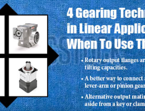
A compact right-angle solution was also a requirement for the application as this would most esthetically work with the design of the table housing. This configuration also provided more gear type options to get the hollow output shaft they desired to be able shaft mount a gearbox onto their existing shaft giving it the smallest envelope size possible.
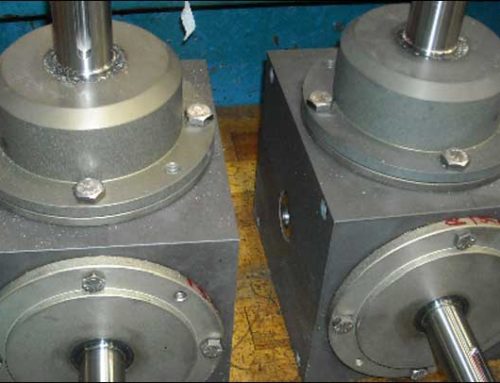
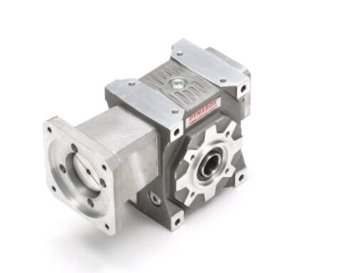
Our industrial manufacturing solution was the Dynabox servo worm gearhead. With three backlash levels, we could provide a 1 arc minute version for super precise positioning, a 5 arc minute version for good positioning, and a 10 arc minute version for general purpose rotary motion.
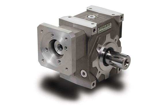
The Dynabox is also available with various output shaft configurations. In this situation the smooth bore with shrink disc connection was optimal. This gave them a zero-backlash drive to shaft connection, which eliminated any additional lost motion.
Because our client’s customers require a variety of indexing speed ranges for each of their unique applications the Dynabox ratio options of 5:1 to 90:1 gave them the flexibility to offer the optimal ratio to meet each application requirement while minimizing the servo motor size.
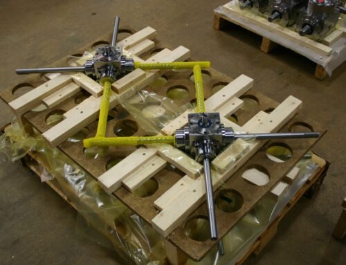
Our customer’s table line encompassed several sizes with different capacities. But within each size, it was possible to use different gearhead sizes and ratios to accelerate the loads. So we work closely with our customer’s application team to analyze each requirement as they came up taking into consideration inertias, acceleration rates, positioning accuracy, and torsional rigidity to help select the optimal gearbox size, ratio, and backlash level to meet the need.
The result has been a successful partnership, marrying two gear drive technologies to provide a key component for automated assembly and process operations.
DieQua works with most of our customers in this way. Our goal is to be an extension of your mechanical drive design team, helping you pick the best gear technology and find industrial manufacturing solutions for your unique needs.
When you have either a power transmission or motion control challenge needing a gearhead, gearbox, or speed reducer, give DieQua a call. We’re sure to have the right solution!