Linear motion for the positioning of tooling, or driving carriages, is a common requirement in automated machinery. Where dual drives are required, precision gearing is critical for positioning performance.
In many applications, a single linear device, such as a ball screw or belt drive, can be driven by a single servo motor, which may or may not include a gearhead to gain additional mechanical advantage. But, for larger or wider loads dual screws are often necessary to provide even or balanced forces. While synchronized master/slave servo motor controls could be used to drive each ball screw independently, precision gearing allows the use of a single servo motor, reducing the expense and complexity of the electronic control system.
A customer of ours recently requested a solution to mechanically link two ball screws in a drive system to provide accurate positioning with a single servo motor. Additional information on several different design elements was necessary to offer the best solution. These included torque, speed, and available mounting space. Several options were available. Determining the best combination required consideration of all these elements.
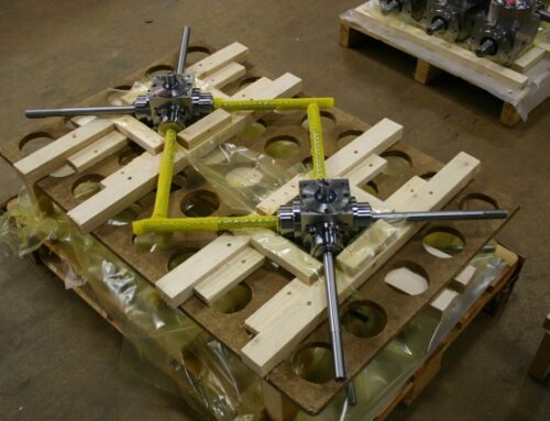
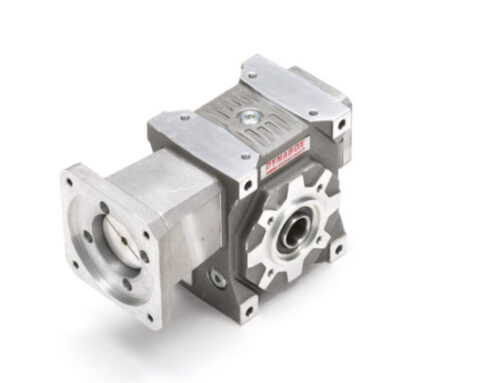
Our typical solution is to drive the ball screws with spiral bevel gearboxes that are connected by a torsionally rigid line shaft or couplings if close together. There are several ways this ball screw drive system can be done, each with its pluses and minuses, depending on the parameters.
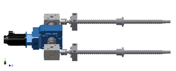
Perhaps the best mechanical solution is to have a center-driven dual-output gearbox with left and right outputs to corner gearboxes driving each ball screw. This ball screw drive system has several advantages. It provides a relatively compact solution, keeping the drive inside the width envelope of the machine. It provides consistent input motion to both corner gearboxes. It also provides the possibility of two stages of speed reduction to optimize gearbox and line shaft sizes, as well as inertia matching for the servomotor.
A point of consideration in this and other similar applications is the span and desired speed of the driving ball screws. Higher speed output requirements would use one type of gear technology, such as a spiral bevel gearbox while slow speed actuation may use another, such as a helical bevel gearbox.
In this case, the overall motor speed-to-screw input speed was to have a 2:1 ratio for relatively high linear speeds. The question was where best to put the 2:1 reduction, in the first drive box or the corner boxes?
To keep all three boxes approximately the same size, it is best to put the ratio in the corner boxes. These boxes would each see half the output torque of the main 1:1 drive box. Doubling the torque through the corner box would mean each of the three boxes would generate the same output torque, regardless of its location.
If the distance between the corner boxes was large and long lineshafts were needed, there could be a possibility of shaft whip or the potential for unwanted frequencies. If the distance between the corner boxes was large and long lineshafts are needed, there could be a possibility of shaft whip or the potential for unwanted frequencies. Calculations for critical speeds would have to be performed. If speed is not an issue the advantage is that smaller and less costly shafts can be used due to lower torque being carried. If the span is short, and standard couplings can be used, then the lineshaft whip isn’t an issue.
If the initial drive box gets a bigger ratio, there are other advantages and disadvantages. The downside is the first box sees more torque. Therefore it will get bigger and more expensive. With the multiplied output torque, the line shafts, or couplings, to the corner boxes also have to get bigger. The only real advantages of putting the ratio in the first box are that the line shafts run slower and there may be some reflected inertia improvements, as the inertia of the lineshafts and corner boxes are reduced by the square of the primary gearbox ratio.
This configuration for this ball screw drive system can work even better if the speed reduction ratio of the application is higher. The possibility of having ratios in two boxes provides a lot more design versatility.
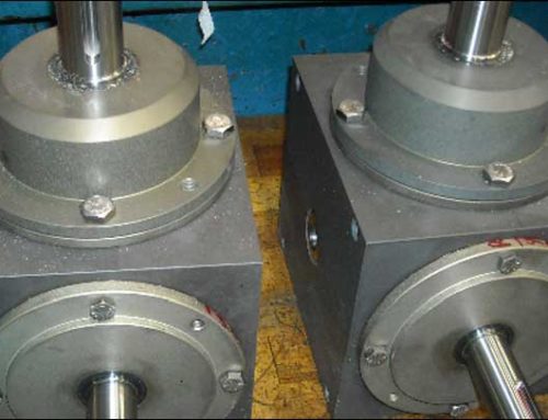
When there is no mounting structure between the screws to install a center drive box an alternative we’ve provided is to fabricate a mounting flange to what is typically the output side of a “T” style 1:1 or 1:2 bevel box. The cross of the “T” now is the input, which allows torque to pass through to the second screw drive box.
While some may be concerned about lost motion at the second screw, we accommodate this by using torsionally rigid torque tubes with flexible ends to compensate for shaft misalignment. In a ball screw drive system, any potentially lost motion due to shaft wind-up is minimized by the mechanical advantage of the screw ratio. This is rarely an issue except in the longest of spans. Larger-diameter torque tubes can always be used to increase rigidity.
Using mechanically linked drives for synchronized motion is really the most reliable design, especially when both axis are following the exact same motion profile. While servo motor manufacturers will lobby for independent drives, the increased complexity of the control and feedback functions will add unnecessary performance risks. Typical anti-mechanics arguments, made by electronic proponents, may apply when using standard industrial gear drives. However, DieQua supplies gear products and connecting components designed and optimized for the speed and positioning requirements of the most demanding automated equipment being developed today.
For these and other types of automation applications where the “mech” part of mechatronics is critical, give DieQua a call. We will help you choose the right product for your unique needs and advise how best to integrate it into your motion system design.