Screw jacks are just one member of the linear motion family, more suitable for relatively low duty cycles. A customer had a noise and wear problem we had to troubleshoot. It highlighted what not to do.
There are two common types of screw jacks. Ball screw jacks have recirculating balls in the threads that reduce friction, and machine, or acme thread, screwjacks have a sliding action similar to a nut and bolt. Ball screws allow more duty cycles, and machine screws allow less.
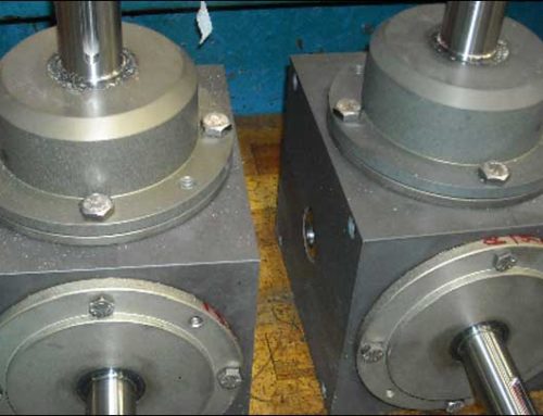
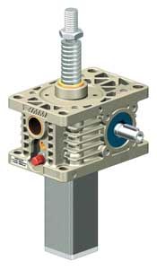
Within these screw jack types, there are two versions. What we call our standing version has the screw itself traveling through the body of the jack, without rotation. Our rotating version has a spinning spindle or screw, that drives a nut along its length.
One of our customers had a European-designed machine with our rotating machine Zimm screw jacks included as the main drive mechanism. It raised and lowered a delivery table via a bracket attached to the traveling nut. He had purchased some replacement nuts over time. But this time he called saying the new nut he just installed was making an awful screeching sound as it neared the jack body.
Considering he had replaced a few nuts in a relatively short period of time we began by asking the preliminary review questions such as what is the load he was lifting and what is the duty cycle. If something in the application changes or if he is running often, this could be a reason for premature wear or damage from previous wear.
The first question is about load because a common mistake many designers make is to select a screw jack based on the load alone. Have a 1-ton load? Pick a 1-ton jack. This can lead to problems as a screw jack’s rating is its static capacity, not its dynamic capacity. As soon as you start moving a load you have to de-rate. The more often or faster you move the load the more you have to de-rate. Therefore, identifying the duty cycle is critical for screw jack selection.
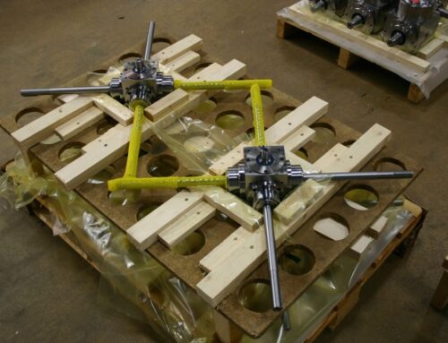
All seemed well with the load and duty cycle so we asked them to send a digital photo of the assembly to see if we could determine anything from the setup (they were in a remote location we couldn’t get to quickly). They did one better by sending us a video of the machine in operation complete with the noise they were complaining about. After viewing the video the problem was immediately apparent.
As mentioned, this customer had our rotating version. The screw jack body is usually fixed, the end of the screw is supported by a radial bearing, and the load is guided and attached to the traveling nut.
However, the video clearly showed there was no bearing support at the top of the screw. As the nut started its descent the free end of the screw started to vibrate like a tuning fork. As it continued downward, the vibration turned into a wobble. As the now screeching nut neared the jack body the uncaptured screw end turned into a whirling dervish that nobody should have thought was normal but had seemingly never been questioned before.
Common mistake number two had been made. Either the load was improperly guided or the system was seriously out of alignment.

Screw jacks can take very little side load. Therefore any side forces, either from weight or misalignment, must be minimized or eliminated. This is usually accomplished by guiding the load with rails, rollers, or linear bearings of some type. It keeps the load moving in the intended direction without undue strain on the nut from something other than the axial load it needs to move.
Aligning the guides to the jack (or vice versa) in its linear direction then becomes one of the critical exercises in mounting screw jacks or any other linear actuator for that matter. Otherwise, it’s like trying to screw in a bolt that isn’t centered on the thread of a nut. It doesn’t want to go in without extreme force and usually results in damage. It seemed clear that the customer was experiencing thread damage to the nut because the screw and the guided load weren’t aligned.
In this customer’s case, it was a relatively easy, but incomplete fix. After some measurements, it seemed the load guides were aligned reasonably well to each other. Opening up the mounting holes on the screw jack base plate allowed the jack body to be better centered while shimming the corners achieved better parallelity. The job was incomplete because they could not support the top of the screw. While it is sometimes ok to leave this unsupported for short lengths, longer screws will wobble due to straightness tolerances and harmonics.
Other customers have alignment problems after the fact, but it is often because of their guide design instead of the screw jack positioning. This can be a bigger problem as misaligned frames or more complex mounted guide systems are not as easy to adjust. That’s why it’s really important to consider component and fabricated structure assembly tolerances in the machine design process. Whenever multiple components or different structures need to be aligned with each other, tighter tolerances may be necessary.
Usually, we try to be heavily involved in the design process, whether it’s screw jacks, gearboxes, or servo gearheads. Allowing us to be an extension of your design team assures consideration of all the relevant design parameters when integrating our products. It’s that kind of assistance that can differentiate us from other suppliers and add value to our relationship.
DieQua is a manufacturer and supplier of a wide array of gearboxes, gearheads, and gearmotors for power transmission and motion control, complimentary shaft connecting and safety components, and screw jack lifting and positioning systems. With decades of combined experience covering a wide range of industries, we have a solution for your unique needs. Give our gearbox consultants a call for help with your next design challenge.