The tried and true method of synchronizing the speed of multiple stations by linking them mechanically through a gearbox system remains a popular option in machine design. This is still seen in printing presses, conveyors, roll forming and packaging lines, just to name a few examples.
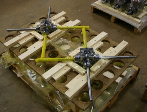
A customer of ours recently requested some assistance in designing a conveyor and feed system for a large pipe cutting operation. The long, heavy pipe was to be loaded on a set of rollers that would then move the pipe into a cutting house where it would be sawed into various lengths.
The rollers were to be spaced several feet apart and required consistent speed to smoothly move the pipe along. There was also an acceleration/deceleration element to the profile, as motion would only commence after the pipe was loaded and stopped when the pipe was in position for cutting.
Now this is where the motion control guys want to put a servo motor on each station and, with drives and master/slave controls, manipulate and match the motor speeds driving the individual rollers. But this is overkill and more expensive in a lot of cases. And trouble shooting in the remote area this application was destined for could be problematic.
Then there are the speed control guys who would drive multiple gearmotors through a single inverter to try to speed match the rollers. This could work where there is a closed loop speed feedback system, but with open loop the gearmotors would likely operate at slightly different speeds. Again, this is probably a more expensive option with all the extra motors and feedback controls needed for each gearmotor.
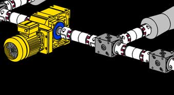
No, in this case a mechanically linked line shaft and gearbox system would result in the simplest drive system with reliable speed matching.
So, what are the issues when devising this system? The first is calculating output torque and speed at each station. The second is to determine how many stations the main power source has to drive and where it will be positioned in the driveline. The third is determining the amount of through torque from station to station to pick line shafts and compare gearbox shaft strength.
Lets take as an example a simple eight station system. We identified, through roller diameters, pipe weights, coefficients of friction and linear speed, that each station requires 72 Nm of torque at 100 RPM. That’s approximately 1 horsepower. So, for 8 stations we need 8 horsepower and will likely use a 10 HP motor operating at a nominal speed of around 1750 RPM.
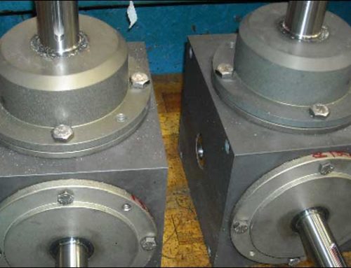
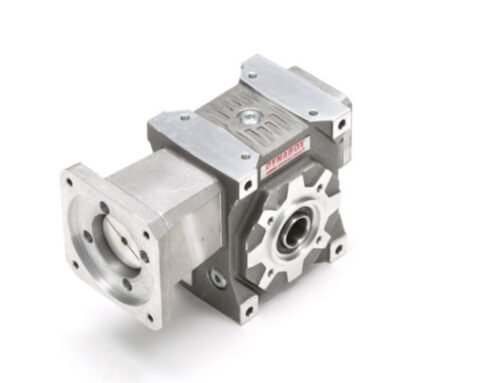
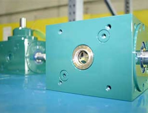
How do we get from 1750 to 100 RPM? Gearboxes! We can put all the ratio in the main drive box and use 1:1 miter boxes to turn the corners or use a lower ratio in the main drive and add some ratio to the bevel boxes. Which is best? It really depends on how many boxes are in the line.
Inherently it’s usually best to put the biggest ratio in the box that drives the individual load, for two reasons. The first is a gearbox’s output capacity is only marginally affected by the ratio, so make it do the work. Secondly, this allows the components on the input side to be smaller because of the lower input torques transmitted.
Unfortunately, spiral bevel gearboxes don’t offer many ratio options from the through shaft on out the pinion. A 2:1 ratio is about the biggest. Unfortunately, that reduces the input shaft diameter. Why is that an issue? It results in reduced through torque capacity.