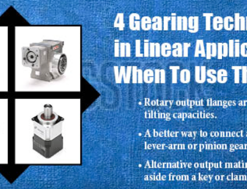
There are a lot of applications where timing the rotation of two elements is required and many of these have one or more of the elements that must physically move position. Examples are coating lines where applicator gap control is necessary, packaging lines where package heights vary, roll formers or die cutters where material thicknesses vary, and machines that require an element to retract for cleaning or set up, among others.
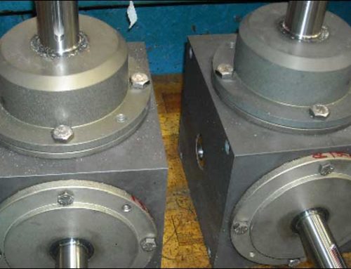
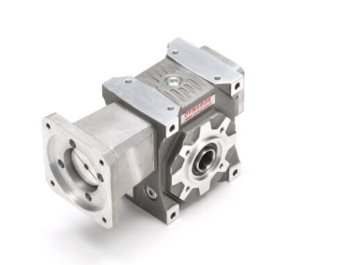
We had a customer that recently approached us with such an application. He wanted to drive two rollers with a single drive. One was to be stationary and one was to be incrementally adjustable for gap control while also allowing for a larger distance adjustment for tooling change and setup. The concept included two right-angle boxes driven on a common line shaft.
The moveable roller and its driving gearbox were to be mounted on a separate carriage, vertically adjusted via a ball screw, and aligned with a dovetail guide system. The customer was originally looking at our hollow shaft spiral bevel gearboxes with keyways. He had planned on inserting a shaft with a long keyway. As the carriage moved, the gearbox would follow and still be able to transmit torque.
Unfortunately, this wasn’t the optimal design to achieve the desired results. Insert shafts with keys are relatively tight fits into their mating bores. Looseness and clearance are not desirable. And that’s what is needed when sliding an insert shaft through a bore without binding due to slight misalignments.
While the customer assured us they could properly align everything, to us it seemed unlikely. The fixed box was to be mounted on one frame, the moving carriage on another, and the guide system on a third. Including the gearbox mounting surface variance, it seemed a huge task to accommodate all the component tolerances. Even small errors would bind the shaft and probably damage the shaft key. So, what to do?
Our suggestion was to use spline shafting and a hollow shaft gearbox with a mating profile. We have used this solution in a number of applications for altering gearbox center distances. Spline shafts typically have a somewhat looser tolerance than standard shafts with keys. This reduces the possibility of binding and shaving the side of the key during adjustment when there is a misalignment.
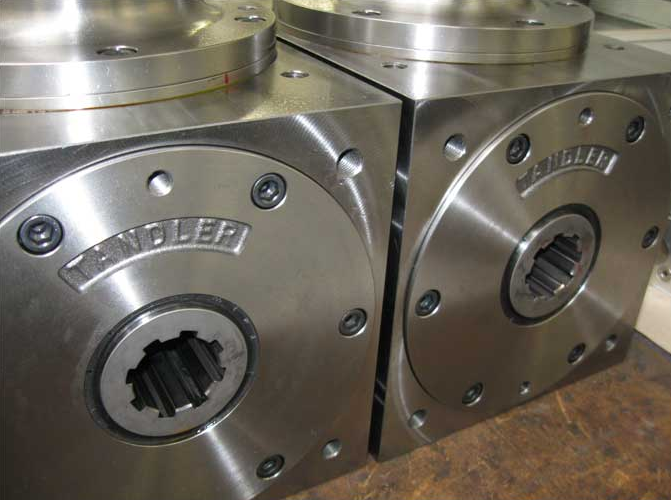
And even with this configuration, alignment is critical. With the shaft supported at one end by a gearbox and the other end by bearing support, parallelity between the shaft and guide system is very important. And shimming the gearbox mounting surface to maintain alignment of its hollow bore is a necessary step.
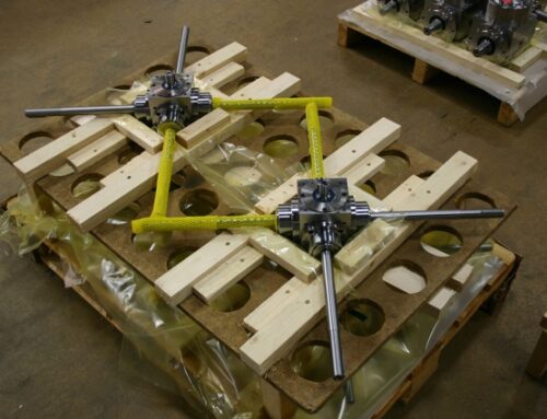
So, the full recommendation we offered went like this. Start with a spline shaft that will get turned and finished on both ends. One end will have a key and plug into a fixed-mounted bevel box with a keyed hollow shaft. The shaft end should be drilled and tapped to draw the insert in tight against a shoulder on the shaft. This will be one end of the shaft support.
The other end should be finished to insert into a self-aligning bearing, as the second shaft support, and be long enough to allow connection of a flexible coupling to a motor shaft that will drive both gearboxes. Although not absolutely necessary, a self-aligning bearing would take up small inaccuracies in mounting the spline shaft.
The carriage assembly supporting the floating gearbox and moveable roller then needs to be aligned with the guide system. In addition, both gearbox surfaces need to be shimmed so the gearbox shafts are parallel with the guides. This is necessary as there may be some parallelity tolerances between the housing surface and shaft bearing bores. The final position of the self-aligning bearing can be determined when there is no spline shaft end movement after testing the travel of the carriage-mounted gearbox. If there is no binding during travel, alignment should be good.
The initial precise design of the frames, guides, and mounting pilots or plates is of course important prior to machine assembly and the final travel test. It’s unlikely that major dimension changes will be possible after fabrication. So tolerances will have to be established for the various mating components to assure a successful operating system.
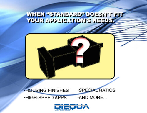
While this seems unwieldy when describing it, it’s actually a common design concept that we have successfully implemented many times over for a variety of machine designs. It’s just that many machine designers haven’t considered it before contacting us, primarily because other gearbox manufacturers aren’t offering that shaft profile as a standard option.
DieQua offers a wide variety of these types of solutions. Whether it’s one of our vast array of standard products or our capabilities for customization, we often have a product that meets the need as well as the know-how to help integrate it into your machine.
So, give our gearbox consultants a call and let us know what you are trying to do. We’ll give you some suggestions that will likely improve the performance, efficiency, and aesthetics of your next project.