Installing a mechanical torque limiter in a heavy-duty motion system is an essential safeguard, especially in applications involving direct human interaction or high-inertia processing equipment. A frequent objection during initial design phases is that high-end protective components can carry a higher upfront cost than the individual parts they safeguard.
However, this perspective overlooks the primary ROI: eliminating catastrophic downtime. Replacing damaged assemblies, sourcing components, and performing emergency installations can result in days of halted production—losses that often exceed the cost of the safety components plant-wide.
The Application: Industrial Oven Hood Lift
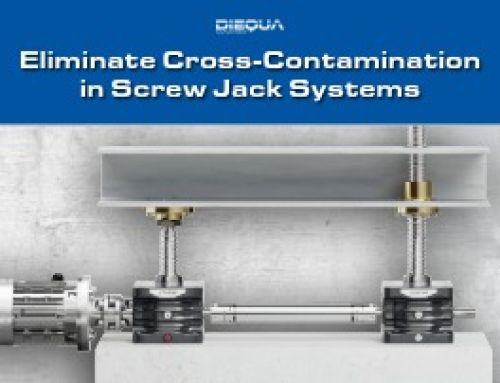
A customer required a complete screw jack lifting system design to elevate the heavy hood of an industrial oven for monthly maintenance and cleaning cycles. The specifications included:
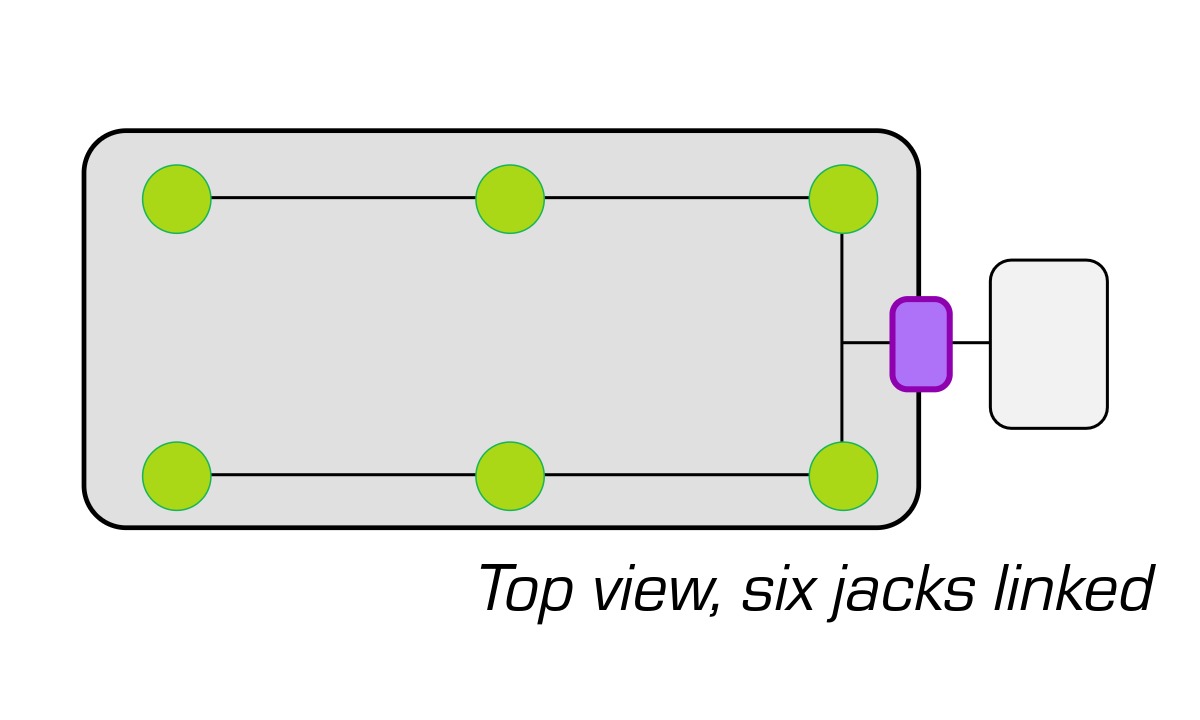
- Drive Configuration: A single high-torque motor driving a multi-axis layout
- Load Distribution: Synchronized lifting across six distinct jack positions
- Risk Factor: Due to low operating duty cycles and the potential for mechanical binding, engineers identified a severe risk: if a single jack jammed, total motor power would concentrate at a single failure point.
To mitigate this, a mechanical torque limiter was integrated directly at the motor output to instantly sense overloads and decouple the drivetrain before structural damage occurred.
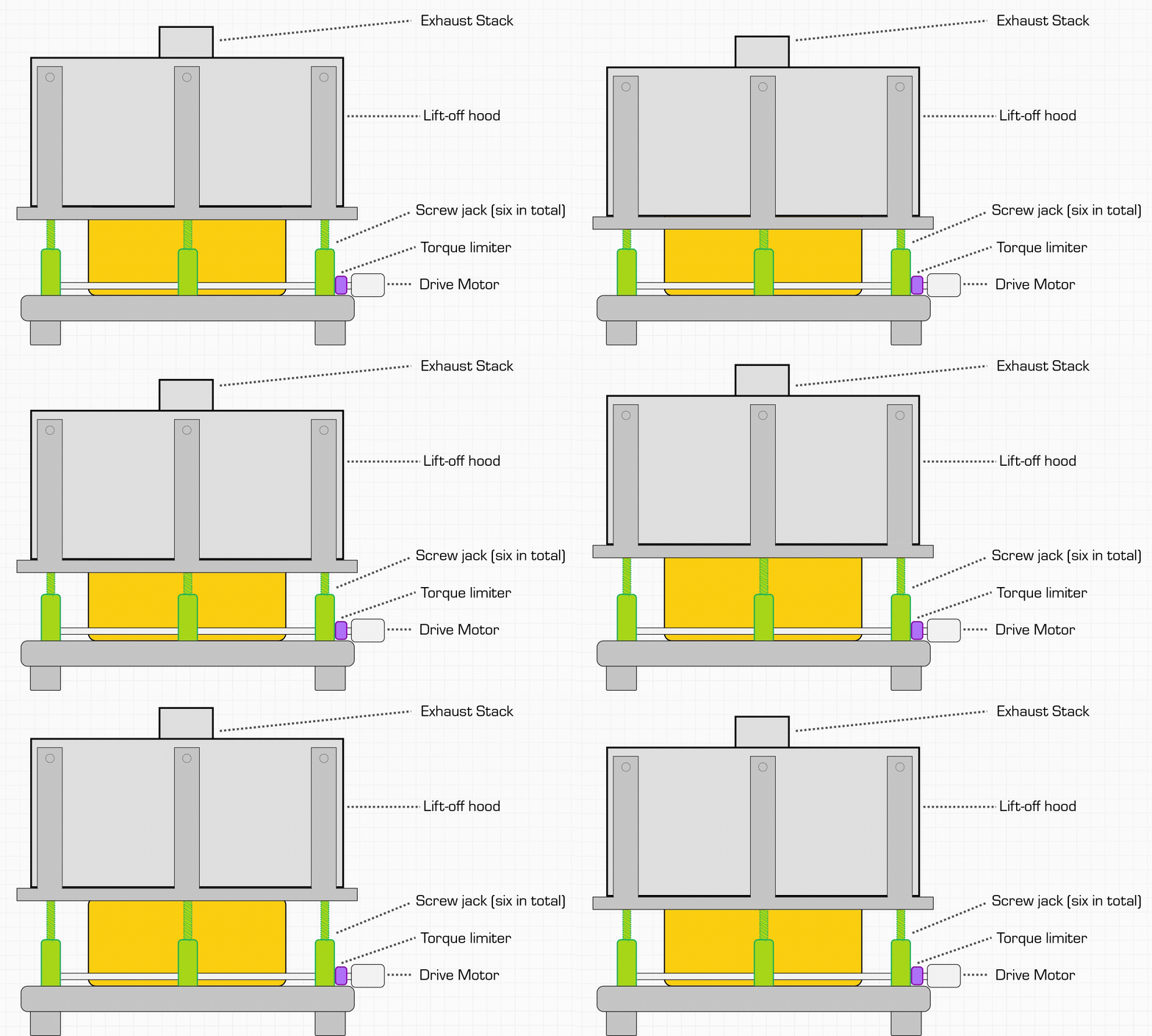
Engineering the Drivetrain Layout
While positioning a torque limiter to the actual load is standard practice, doing so in this multi-jack architecture introduced secondary risks. If a remote limiter tripped while others continued driving, severe structural twisting, shaft bending, and mechanical binding would ensure.
To ensure uniform response:
- Centralized Disengagement: The limiter was coupled directly to the primary motor shaft, ensuring the entire system disengaged simultaneously under an overload event.
- Component Up-rating: Individual jacks were engineered one size larger to ensure static safety factors exceeded the nominal cumulative torque required.
- Rigorous Verification: Gearbox ratios, line-shaft torsional rigidity, intermediate couplings, and system efficiencies were meticulously calculated to determine precise motor sizing.
Test: An Unexpected Trip
During initial factory commissioning, the system was powered on and the torque limiter immediately tripped.
After re-verifying the guide alignment and double-checking mathematical load calculations, a second test was executed. The result? Another fault trip identical to the first.
Suspecting a premature release or miscalibration, the mechanical unit was temporarily bypassed with a standard shaft coupling to allow testing to proceed. With the bypass active, the motor engaged, and with the heavy initial groan, the oven hood began its ascent.
Root Cause Analysis: Inertia vs. Instantaneous Torque
The removed torque limiter was brought back to our facility for bench testing, where it functioned perfectly within its rated parameters. To uncover the root cause, the customer integrated high-resolution amp-draw monitoring equipment during operation.
The data revealed the culprit:
- Inrush and Acceleration Spikes: Because power was pulled directly from the main utility line, the motor attempted to instantaneously accelerate the massive rotational inertia of the entire multi-axis drive train while simultaneously overcoming static friction.
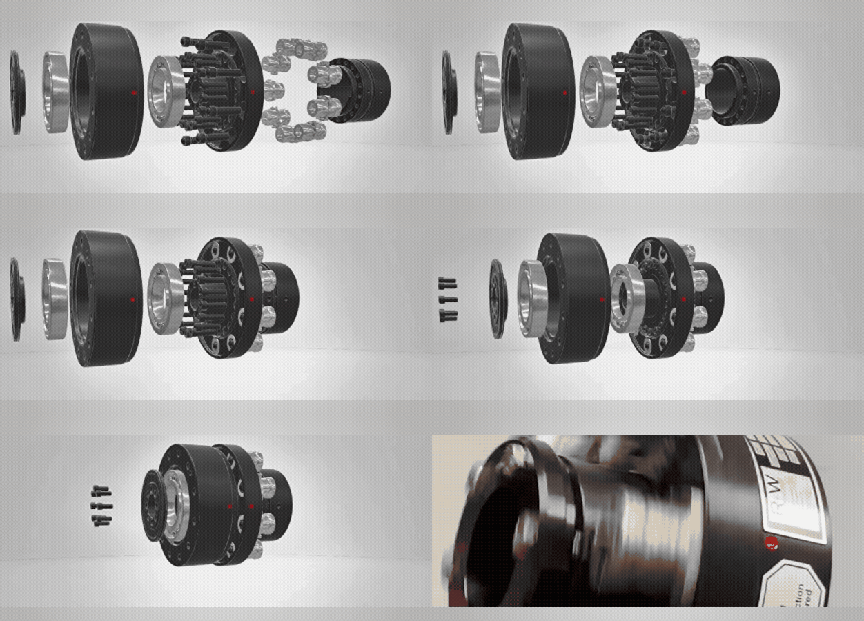
- Mechanical vs. Electronic Response: This generated a massive initial current rush and a transient peak torque spike that far exceeded normal running loads. While programmable electronic drives can be configured with ramp-up delays, mechanical torque limiters are engineered to be high-speed, deterministic safety devices that disengage instantly upon reaching their threshold.
Peak starting torque can often be 2x to 3x higher than running torque, which explains why the safety threshold was tripped at the onset.
The Solution: Optimized Acceleration Control
The fix was straightforward: integrating an electronic soft start (or VFD acceleration ramp) to control motor starting current and smooth out initial rotational acceleration. This controlled ramp-up kept starting torque safely below the disengagement threshold, allowing the mechanical torque limiter to remain armed while the entire motion system operated flawlessly.
Partner with DieQua’s Engineering Team
Complex motion control applications demand careful evaluation of transient loads, system inertia, and mechanical safety limits. Collaborating closely during the initial design phase ensures that protective components and drive architectures are precisely matched to your operational realities.
Contact our engineering team today to discuss your next precision drive application. We’re happy to help you size gearboxes, specify safety couplings, or engineer custom systems.