Machine builders face a recurring design challenge in dynamic motion control: achieving high tilting-moment stiffness and reliable right-angle reduction without adding unnecessary envelope size or external support bearings.
While multi-stage planetary gearheads remain a standard choice for inline precision, they are not always the optimal choice for high-ratio, right-angle setups where radial/axial stability takes priority over high-duty thermal efficiency.
For applications requiring high single-stage reduction ratios, high overhung load capacity, and compact machine integration, right-angle servo worm gearheads offer a mechanically efficient design path. Integrating an ISO 9409-1 rotary output flange directly onto the gearhead further improves rigidity and integration.
Here are four mechanical design advantages of using a rotary flange output in high-load servo applications.

1. Increased Tilting Moment Stiffness Under Heavy Loads
Standard cantilevered output shafts can flex when subjected to severe radial, axial, or tilting forces.
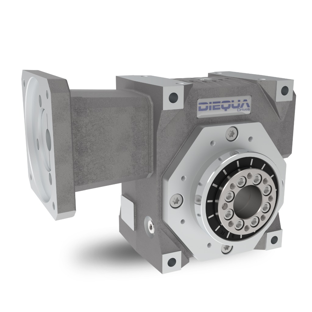
Rotary flange outputs feature large-diameter internal bearings positioned directly beneath the mounting surface. This geometry significantly increases both tilting moment stiffness and torsional rigidity.
When driving heavy indexing tables, robot base axes, or dynamic rack-and-pinion gantries, the rotary flange interface handles aggressive moment loads directly, minimizing shaft deflection and eliminating the need for external pillow block supports.
2. Simplified Mechanical Interface and Envelope Savings
In high-density machine designs, reducing overall part count directly impacts long-term reliability. Traditional shafted gearheads often require additional components—such as flexible jaw couplings, external flange blocks, or custom shaft adapters—to transfer power to the driven load.
An integrated rotary flange simplifies the drivetrain configuration:
- Direct Component Mounting: Pinions, rotary dial plates, and end effectors bolt directly to the flange face.
- Elimination of Coupling Backlash: Removing intermediate shaft couplings eliminates a common source of mechanical compliance, keyway wear, and windup.
- Compact Perpendicular Footprint: The right-angle worm configuration aligns the servo motor parallel to the machine frame, keeping total envelope depth to a minimum.

3. High Single-Stage Ratios & Mechanical Trade-Offs
Achieving reduction ratios above 10:1 with inline planetary gearheads generally requires adding a second or third planetary stage. Multi-stage planetary units increase overall length, mass, and mechanical complexity.
Servo worm gearheads provide reduction ratios from 5:1 up to 90:1 in a single gear set, allowing significant speed reduction and torque multiplication in a single housing.
- Engineering Consideration: Because worm gearing relies on sliding friction rather than rolling contact, single-stage efficiency decreases at higher reduction ratios. For high-duty cycle applications operating continuously at high input speeds, thermal ratings must be calculated alongside mechanical torque limits to avoid thermal overload. However, for indexing, positioning, and intermittent duty cycles, the compact single-stage ratio provides a cost-effective reduction method.

4. Precision Motion Control & Backlash Management
Unlike legacy power-transmission worm reducers, precision servo worm drives utilize ground tooth profiles and dual-lead backlash adjustment mechanisms. This allows output backlash levels to be set below 1 arcminute for high-accuracy positioning applications.
Additionally, the continuous tooth engagement of a worm drive provides inherent dampening against shock loads and continuous, low-vibration operation—making it well-suited for high-cycle automation and noise-sensitive assembly cells.
Sizing & Selection Considerations
-
Rotary Indexing Tables: Direct mounting minimizes bending moments on the drive during rapid index cycles.
-
Compact Work Cells: Perpendicular motor orientation prevents motor overhang into operator walkways or adjacent machine stations.
-
Rack-and-Pinion Linear Drives: Mount pinions directly to the flange face to maximize stiffness in dynamic gantry axes.
Next Steps for Drive Sizing
When evaluating right-angle servo options for high moment loads, calculate your application’s required tilting moment stiffness, radial load center, and duty cycle before specifying a frame size.
Download our Rotary Flange Drive Sizing Worksheet to review thermal vs. mechanical rating limits, or consult our engineering team for assistance with inertia matching and moment load calculations.