Series L – Line Shafts
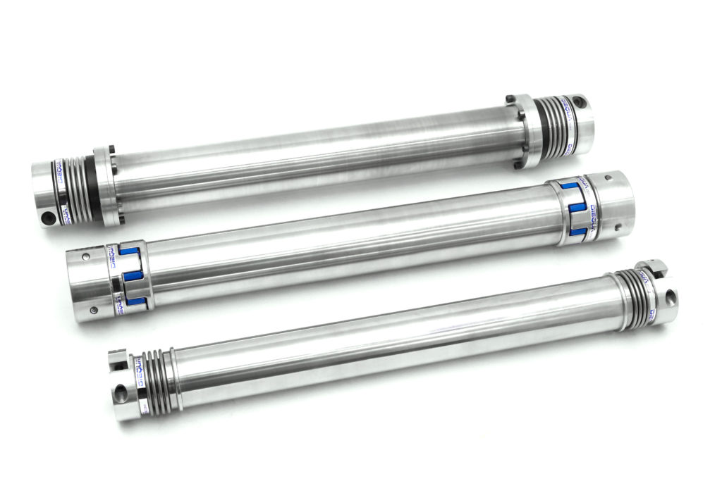
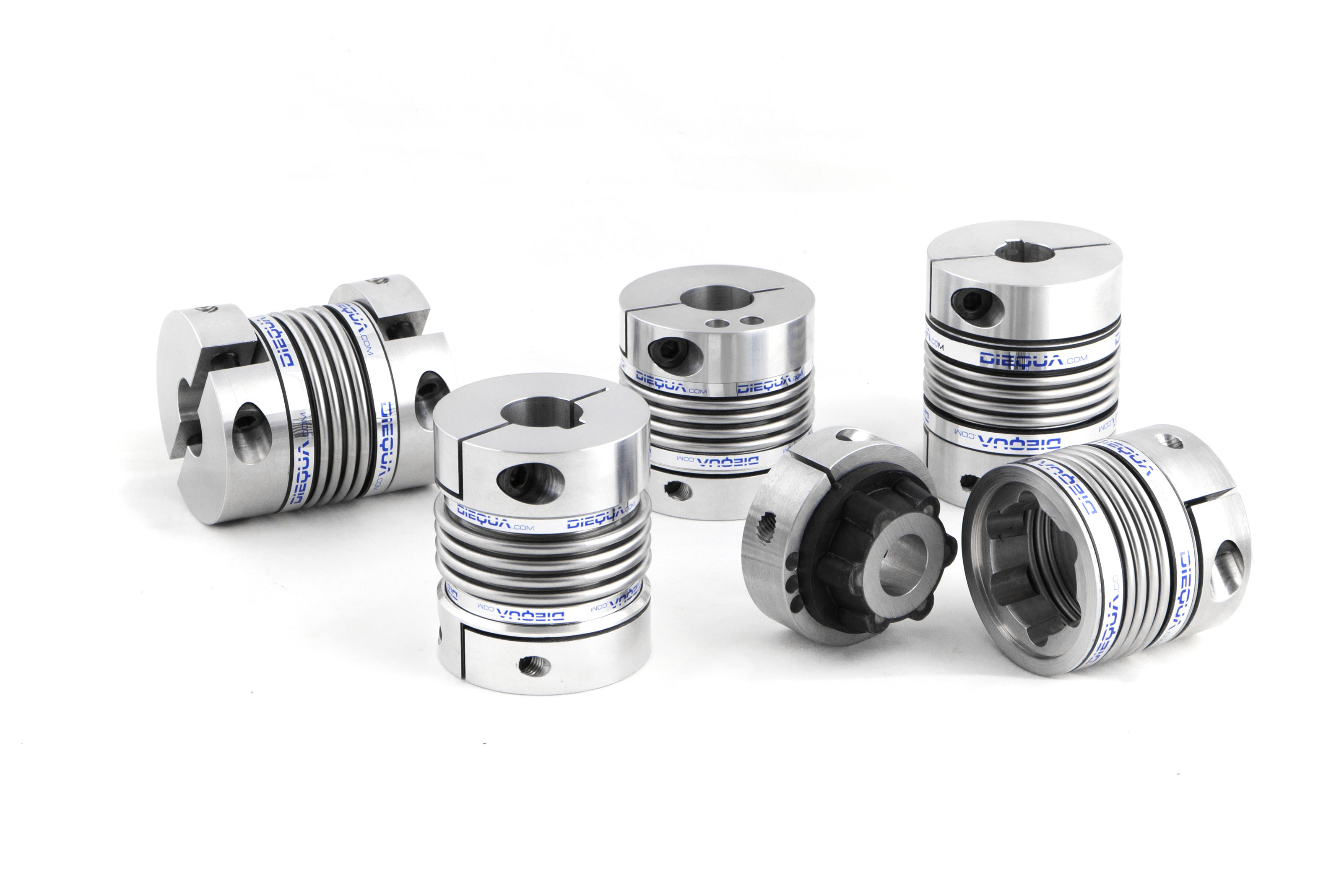
Our Series L line shafts and spacer couplings offer zero-backlash torque transmissions over long spans, without the need for intermediate support.
- 10 – 660 Nm
- Radial installation & Removal possible
- Low moment of inertia
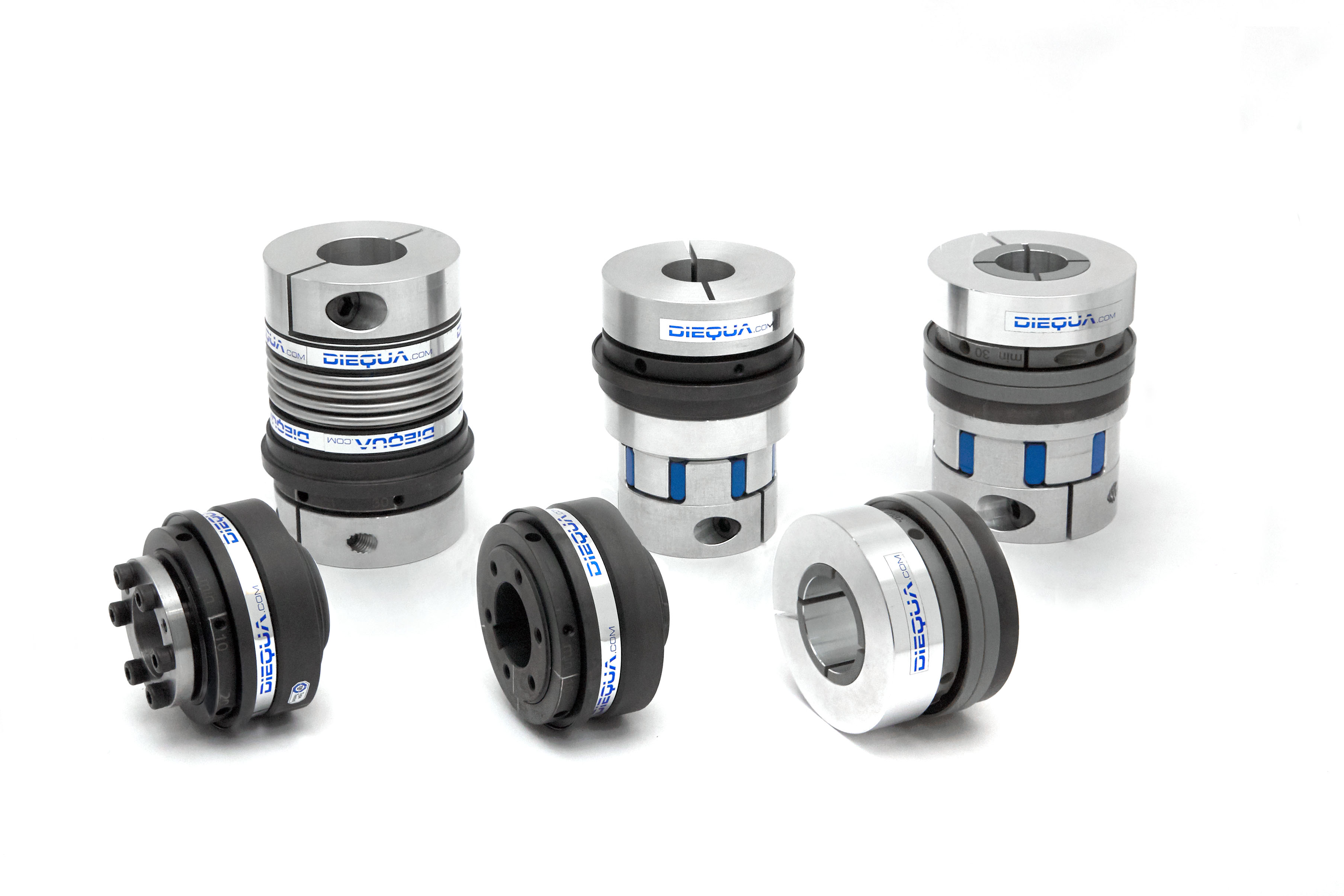
- 3 Models of Line Shaft Couplings: Provides a variety of connection options including clamp hubs to maximize performance and design versatility.
- Customized Lengths: Provides the specific span necessary for each individual application.
- Zero Backlash: Provides exact position for precise rotary motion.
- Low Inertia: Torque tube design reduces weight for faster acceleration with less torque.
- Misalignment Compensation: Allows for angular, axial, and parallel misalignment between the connected shafts.
- Torsional Rigidity Control: Alternate flexible elements and torque tube materials increase or decrease torsional rigidity as required.
- Maintenance Free: No moving parts means virtually unlimited life with proper mounting.
- Non-Standard Applications: Customized line shaft designs with dimension variances, different tolerances, or alternate materials are available for these spacer couplings upon request.
- Download the Catalog
- Download CAD Drawings (See the Charts Below)
- Request more Information
What’s Next?
Line Shaft Overview:
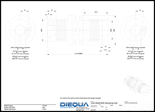
Model LB - Line Shaft with Clamping Hub
Design Description: A three piece design with two compressible hubs and a drop in center tube section. Flexible elements are stainless steel bellows, with internal supports for tube weight support. Shaft connection is by a single screw clamp. Lengths are custom produced.
Bore Diameters: Metric or inch bores from 5-60 mm, or 0.20-2.36 inches. Keyways are optional for ALL sizes.
Temperature Range: From as low as -30° C to as high as +120° C (3.6° F to 270° F). High temperature options available.
Sizes: LB-10, LB-30, LB-60, LB-150, LB-200, LB-300, LB-500
Application Example:

Sizing Chart:
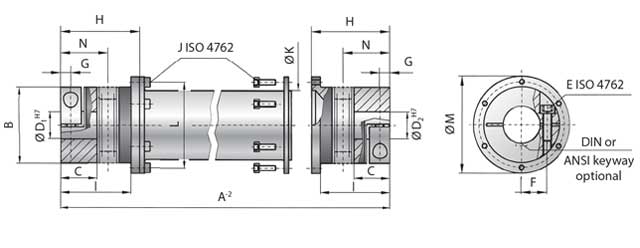
| LB | 10 | 30 | 60 | 150 | 200 | 300 | 500 | |
|---|---|---|---|---|---|---|---|---|
| Rated torque (Nm) | T KN | 10 | 30 | 60 | 150 | 200 | 300 | 500 |
| Overall Length min. to max. (mm) | A⁻² | 110 - 6,000 | 140 - 6,000 | 170 - 6,000 | 190 - 6,000 | 210 - 6,000 | 250 - 6,000 | 260 - 6,000 |
| Outside Diameter Clamping Hub (mm) | B | 40 | 55 | 66 | 81 | 90 | 110 | 123 |
| Fit length (mm) | C | 16 | 27 | 31 | 35.5 | 40.5 | 43 | 50 |
| Inside Diameter H7 (mm) | D 1/2 | 5 - 20 | 10 - 28 | 12 - 32 | 19 - 42 | 22 - 45 | 30 - 60 | 35 - 60 |
| Distance between centers (mm) | F | 15 | 19 | 23 | 27 | 31 | 39 | 41 |
| Distance (mm) | G | 5 | 7.5 | 9.5 | 11 | 12.5 | 13 | 17 |
| Length Bellows body (mm) | H | 44.5 | 57.5 | 71 | 78 | 86 | 94 | 110 |
| Distance (mm) | I | 38.5 | 51 | 61 | 69 | 75.5 | 81 | 96 |
| Outside Diameter Tube Section (mm) | K | 35 | 50 | 60 | 76 | 90 | 100 | 110 |
| Bolt Hole Circle (mm) | L | 45 | 62.5 | 71.5 | 88 | 100 | 120 | 132 |
| Outside diameter flange (mm) | M | 52 | 70 | 80 | 98 | 110 | 135 | 148 |
| Download - 2D DWG | DWG | DWG | DWG | DWG | DWG | DWG | DWG | |
| Download - 2D PDF | ||||||||
| Download - 3D STP | STP | STP | STP | STP | STP | STP | STP | |
Model LBS - Line Shaft with Split Clamping Hub
Design Description: A torsionally rigid economical design consisting of integral stainless steel bellow ends attached to the torque tube. A removable hub half allows for easy mounting. Two tightening bolts connect the hub halves for a compression fit. Lengths are custom manufactured.
Bore Diameters: Metric or inch bores from 5-60 mm, or 0.25-2.36 inches. Optional keyways available upon request.
Temperature Range: From as low as -30° C to as high as +120° C (3.6° F to 270° F). High temperature options available.
Sizes: LBS-10, LBS-30, LBS-60, LBS-150, LBS-300, LBS-500
Application Example:
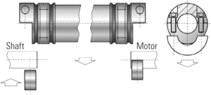
Sizing Chart:
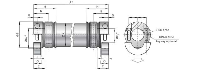
| LBS | 10 | 30 | 60 | 150 | 300 | 500 | |
|---|---|---|---|---|---|---|---|
| Rated torque (Nm) | T KN | 10 | 30 | 60 | 150 | 300 | 500 |
| Overall Length min. to max. (mm) | A⁻² | 100 - 6,000 | 130 - 6,000 | 160 - 6,000 | 180 - 6,000 | 240 - 6,000 | 250 - 6,000 |
| Outside Diameter Clamping Hub (mm) | B | 40 | 55 | 66 | 81 | 110 | 123 |
| Fit length (mm) | C | 16 | 27 | 31 | 34.5 | 42 | 50 |
| Inside Diameter H7 (mm) | D 1/2 | 5 - 20 | 10 - 28 | 12 - 32 | 19 - 42 | 30 - 60 | 35 - 60 |
| Distance between centers (mm) | F | 15 | 19 | 23 | 27 | 39 | 41 |
| Distance (mm) | G | 5 | 7.5 | 9.5 | 112 | 14 | 17 |
| Length Bellows body (mm) | H | 39.5 | 52 | 64 | 72 | 83 | 96 |
| Clamping Length (mm) | I | 10 | 15 | 19 | 22 | 28 | 33.5 |
| Outside Diameter Tube Section (mm) | K | 35 | 50 | 60 | 76 | 100 | 110 |
| Length (mm) | O | 11.5 | 17 | 21 | 24 | 30 | 35.5 |
| Shaft Average Value (mm) | N | 25 | 34 | 41 | 47 | 56 | 66 |
| Download - 2D DWG | DWG | DWG | DWG | DWG | DWG | DWG | |
| Download - 2D PDF | |||||||
| Download - 3D STP | STP | STP | STP | STP | STP | STP | |
| For Full Tech Details Download Catalog | |||||||
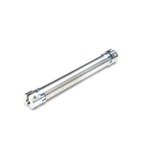
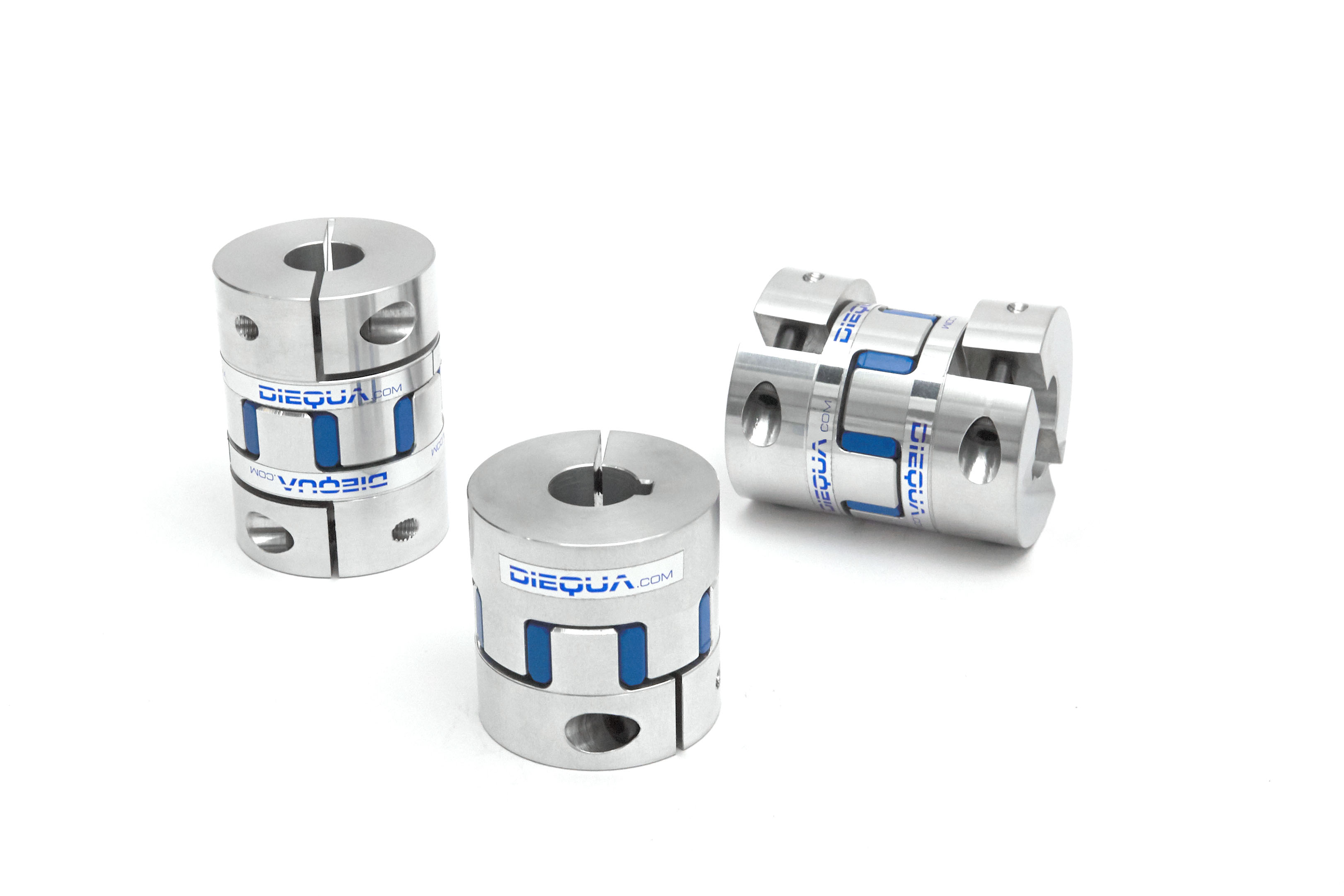
Model LE - Elastomer Insert Line Shaft with Split Clamping Hub
Design Description: Our most cost effective model! The flexible elements are zero backlash elastomer jaw style couplings, with a variety of insert materials, that are integrated with the torque tube. Split half hubs connect to shafts with two screws. Lengths are custom manufactured.
Bore Diameters: Metric or inch bores from 5-60 mm, or 0.25-2.36 inches. Keyways are available upon request.
Temperature Range: Download the catalog for Temperature range.
Sizes: LE-10, LE-20, LE-60, LE-150, LE-300, LE-450
Application Example:
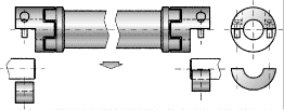
Sizing Chart:
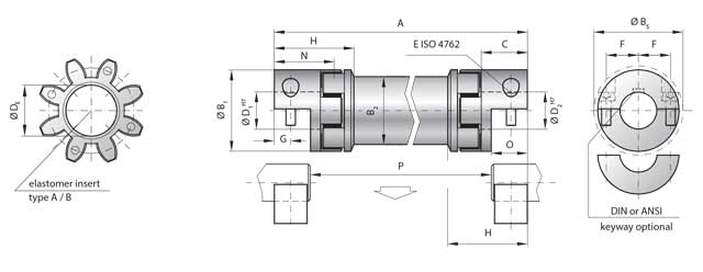
| LE | 10 | 20 | 60 | 150 | 300 | 450 | |
|---|---|---|---|---|---|---|---|
| Type (Elastomer Insert) | A | B | A | B | A | B | A | B | A | B | A | B | |
| Rated torque (Nm) | T KN | 12.5 | 16 | 17 | 21 | 60 | 75 | 160 | 200 | 325 | 405 | 530 | 660 |
| Max. Torque (Nm) | T Kmax | 25 | 32 | 34 | 42 | 120 | 150 | 320 | 400 | 650 | 810 | 1060 | 1350 |
| Overall Length (mm) | A | 95 - 4,000 | 130 - 4,000 | 175 - 4,000 | 200 - 4,000 | 245 - 4,000 | 280 - 4,000 |
| Outside Diameter Hub (mm) | B1 | 32 | 42 | 56 | 66.5 | 82 | 102 |
| Outside Diameter Tube (mm) | B2 | 28 | 35 | 50 | 60 | 76 | 90 |
| Outside Diameter with screw head (mm) | Bs | 32 | 44.5 | 57 | 68 | 85 | 105 |
| Fit length (mm) | C | 20 | 25 | 40 | 47 | 55 | 65 |
| Inside diameter range H7 (mm) | D1/2 | 5-16 | 8-25 | 14-32 | 19-36 | 19-45 | 24-60 |
| Maximum Inside diameter of elastomer | DE | 14.2 | 19.2 | 26.2 | 29.2 | 36.2 | 46.2 |
| Distance between centers (mm) | F | 10.5 | 15.5 | 21 | 24 | 29 | 38 |
| Distance (mm) | G | 7.5 | 8.5 | 15 | 17.5 | 20 | 25 |
| Coupling length (mm) | H | 34 | 46 | 63 | 73 | 84 | 97 |
| Shaft Average Value (mm) | N | 26 | 33 | 49 | 57 | 67 | 78 |
| Length (mm) | O | 16.6 | 18.6 | 32 | 37 | 42 | 52 |
| Download - 2D DWG - COMING SOON | |||||||
| Download - 2D PDF - COMING SOON | |||||||
| Download - 3D STP | STP | STP | STP | STP | STP | STP | |
| For Full Tech Details Download Catalog | |||||||
Coupling Insert Options, Temperature Ranges, and Stiffness Ratings:
The elastomer inserts are made of thermoplastic polyurethane (TPU), in a variety of shore values. To provide different stiffness and vibration damping characteristics, optional Hytrel® material can be offered for higher temperature applications.
The inserts are pre-stressed during assembly which provides zero backlash, more consistent load sharing, and improved restoring forces for precise positioning and repeatability.
For information on shaft misalignment, torsional stiffness and other details about the elastomer inserts, please download the catalog.
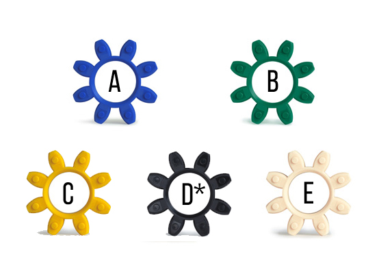
* Due to the electrically conductive properties of the insert, electrostatically charging of the coupling is prevented. This eliminates sparks during normal operation in explosive areas. Technical data is available upon request.
The values of the relative damping were determined at 10 Hz and 20˚C.
Other Models Available
Why Choose a Line Shaft?
Spacer couplings and lineshafts offer zero backlash torque transmissions over long spans of time. Will not require the need for intermediate support.
