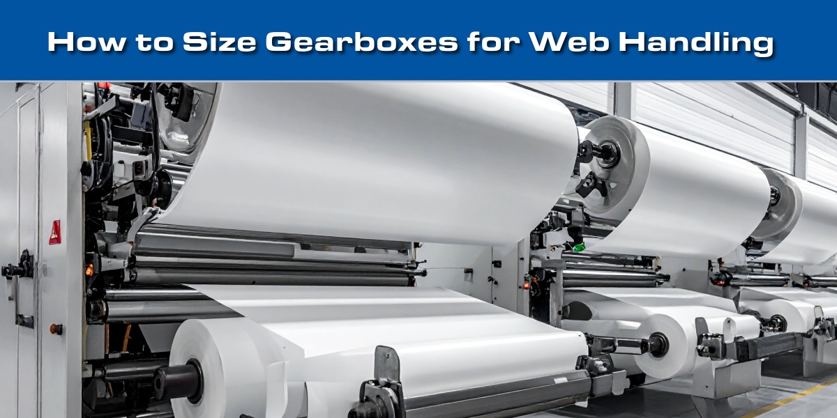
Winding and unwinding coils of continuous material such as flexible packaging, film, paper, and foil requires precise variable speed operation and dynamic tension control. Maintaining constant web tension protects material thickness, while managing variable rotational speed ensures steady linear throughput.
Selecting a gearbox for winder and unwind stands differs from standard continuous-speed applications. Because roll diameter and mass change constantly throughout a cycle, standard horsepower-to-speed formulas are insufficient.
Let’s cover how to size winder gearboxes, manage emergency stops, and select the right power transmission hardware for converting and packaging machinery.
The Core Physics: Speed vs. Torque in Roll Building
In winder applications, output RPM and torque fluctuate continuously across the roll cycle:
- Variable Speed: As material builds up on the take-up roll, the circumference expands. To maintain a constant linear speed (feet/minute), the rotational speed (RPM) must decrease as the roll diameter grows.
- Variable Torque (Torque increases as roll grows): As material layers build, the increasing radius creates a longer lever arm against the center shaft, requiring maximum twisting moment at full roll diameter.
Because peak torque occurs at the lowest operating speed, a winder gearbox must be sized for the maximum torque required at the largest roll diameter, not the starting core condition.
Step-by-Step Winder Gearbox Sizing Calculations
To properly size a gearbox for winder or unwind stand, calculate the maximum operational torque required at the largest roll diameter:
1. Calculate Web Tension (Force): Web tension is defined in Pounds per Linear Inch (PLI) based on material sensitivity. Multiply PLI by the total web width to find the required linear pull force:
TensionTotal = PLI × WidthWeb
2. Calculate Maximum Torque: Multiply total web tension by the maximum outer roll radius (in inches) to determine the peak continuous torque requirement:
TorqueMax = TensionTotal × RadiusMax
Note: Divide total inch-pounds by 12 to convert to lb-ft if required by drive sizing software.
3. Determine Minimum RPM: Calculate the lowest rotational shaft speed occurring at full diameter:
If the gearbox handles the peak torque at this lowest RPM stage without exceeding thermal or mechanical limits, it will successfully run the full roll cycle.
Overcoming Critical Edge Cases: High Core RPM & E-Stops
Standard continuous torque ratings don’t tell the whole story. Design engineers must verify two critical operating extremes:
-
High RPM Core Starts: At the bare core, the input motor speed will be highest. While this temporary high speed can generate friction, the roll diameter builds rapidly, dropping RPM before thermal heat limits are reached. Verify that the gearbox’s maximum input RPM rating is not exceeded during core startup.
-
Emergency Stops & Web Jams (Inertia Load): Stopping a heavy roll quickly during a web jam or emergency stop (E-stop) introduces high inertia loads. E-stop torque is calculated using motion control acceleration/deceleration formulas (Torque = Inertia x Angular Deceleration). Because speed is lowest at maximum inertia, peak E-stop torque is often lower than peak operational torque. Premium industrial gearboxes can absorb 2x to 3x their rated torque during brief deceleration spikes.
Key Mechanical Features to Look For
When evaluating gearbox styles for web handling stands, consider these gearboxes for common machines.
| Machine Location/Function | Recommended Gearbox | Key Mechanical Feature |
|---|---|---|
| Main Winder / Unwind Drives | Tandler HW Series | Shaft-mount right angle, metric/hollow bore, high tooth-to-tooth accuracy |
| Continuous Turret Winders | GearSync Helical Bevel Series | Low backlash, right-angle, high load capacity for heavy roll indexing |
| High Precision Servo Indexing | Precision Worm (DPW) | Smooth torque transmission, extremely low backlash, compact right-angle layout |
1. Main Roll Drives: Tandler Series HW Spiral Bevel Gearbox
-
Optimized Ratios: Standard ratios of 4:1 and 5:1 keep motor RPM in an efficient operating range while offering torque multiplication at core speeds.
-
Shaft-Mount Design: Direct hollow-bore shaft mounting on the roll journal eliminates external couplings and reduces line footprint. Available with metric bores, keyways, splines, and shrink discs across 8 frame sizes.
-
Smooth Rotational Velocity: Precise tooth geometry delivers uniform angular velocity within each revolution, preventing tension spikes, web stretch, or coating flaws on sensitive films.
2. Turret Winder Indexers: GearSync Helical Bevel & Precision Worms
-
Turret Roll Swapping: Turret winders rotate 180° to move a new core into position while splicing without stopping the main web line.
-
Positioning Accuracy: Low-backlash helical bevel gearboxes and servo worm gearheads provide the mechanical rigidity needed to swing heavy rolls smoothly into alignment.
Consult with Motion Control Engineers
Whether you are designing custom packaging machinery, retrofitting flexible converting lines, or selecting drives for high-speed roll stands, properly sizing variable-speed gearboxes prevents scrap and downtime.
Contact DieQua’s engineering support team to review your PLI tension ratings, inertia profiles, and shaft configurations for optimal selection.